by Chu Moy

This article describes modifications to an acoustic simulation circuit for headphones that appeared in a magazine article called “Improved Headphone Listening” by Siegfried Linkwitz (Audio, December 1971). It is a simple RC-type filter that creates a more realistic sound image in headphones by electronically mimicking the “shaded” interchannel crossfeed of normal hearing. The circuit was based on a design published by Benjamin Bauer ten years earlier, but the Linkwitz version does not use inductors and is less sensitive to load impedance. (Crossfeed filters should not be confused with virtualizers, which use digital signal processing to simulate binaural or externalized 3D sound.) These modifications improve the sound of Linkwitz filter and optimize the circuit to work with headphone amplifiers.
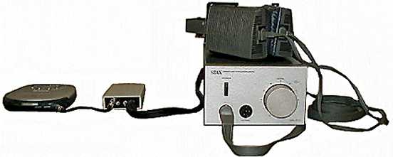
I tested the modifications with my DIY pocket headphone amplifier (shown above), the Musical Fidelity X-Cans (v.1) headphone amplifier, Sennheiser 465 and Sennheiser HD600 headphones and the Stax SRS-3030 electrostatic headphone system. The source was a Panasonic SL-SX500 CD player. The filter can drive either a headphone amplifier or headphones directly with the headphone amplifier as the source. I tested the original filter directly connected to the HD465 phones and fed by the X-Cans. The modified filter was tested both ways: as the source to headphone amplifiers and directly connected to both headphones. Putting the filter before the amplifier eliminates any impedance interaction between the filter and headphones.
For more information about the original Linkwitz circuit, please refer to the Audio magazine article cited above. For more information about the Bauer circuit and acoustic simulators generally, see Technologies For Presentation of Surround Sound in Headphones and The Psychoacoustics of Headphone Listening. For information on commercial crossfeed filters, see A Quick Guide to Headphone Accessories.
Background
At work, I listen to music with headphones several hours each day. My system is a Musical Fidelity X-Cans amplifier and a pair of Sennheiser HD465 headphones (discounted 50% from a liquidation house!). The source material is either CD or FM radio. Although the audio reproduction is excellent, I cannot listen to this system for more than four hours without suffering headaches, caused by the super-stereo effect that is characteristic of headphone listening.
Stereo recordings are meant to be heard through loudspeakers. Headphones create a soundfield that is unnaturally spacious, in which some sounds seem to be crowded around each ear. A few months ago, I did some research into the problem. Headphone amplifiers from HeadRoom Corporation had a built-in crossfeed circuit to mitigate this unpleasant effect. However, I did not want to replace the X-Cans amplifier. Then I ran across a stereo crossfeed circuit in an old issue of Audio Magazine, which seemed to do something very similar to HeadRoom’s audio image processor.
I upgraded the design with higher quality parts, which I ordered from Digi-key Electronics and Mouser Electronics. The circuit was assembled on a 2″ x 1.75″ piece of printed circuit protoboard and put in a PacTec case from Radio Shack (RS 270-211). The front panel had two mini-stereo jacks (for the input and output), and a bypass toggle switch. (See A Pocket Headphone Amplifier for more information about purchasing parts.) The output of the X-Cans went to the input of the filter, and the headphones plugged into the output. After a month of listening with the Linkwitz circuit, I became dissatisfied with the sound quality. It did eliminate the super-stereo effect, but introduced other sonic problems.
First, the high frequencies were severely attenuated compared to the original signal, despite the built-in treble boost in each channel. The imbalance imparted a muffled effect to all kinds of music. With some vocalists (such as Barbra Streisand – yes, I am a fan), voices took on a “thick” quality. I suspected that the effect was caused by phase anomalies at the crossover point interacting with phasey artifacts in recordings.
Second, the level of crossfeed was a bit excessive for my tastes. The soundstage was pulled inward, away from the ears, but I felt as though I was sitting in the back of an auditorium with heavily padded walls. Flipping the bypass switch restored the spaciousness and reverb at the expense of the benefits of the crossfeed.
Third, the filter did not drive headphones well with a headphone amp input. The original circuit was designed to be connected to the output of a power amplifier. Running it from the speaker outputs of a 15W receiver produced ample volume. Headphone amps, on the other hand, huff and puff along at a relatively measly 100mW maximum output. A few Thevenin computations also revealed that the output impedance of the filter was slightly frequency dependent and varied from 61 to 73 ohms. My Sennheiser HD465s were rated at 60 ohms. These factors explained why I had to keep the X-Cans volume control at 75% rotation to achieve acceptable listening levels.
The Modifications

Figure 1
The original circuit (figure 1) crossfeed frequencies below 700 Hz (figure 2). Linkwitz noted that the low frequency blending raised the bass response in each channel by about 3dB. He designed a 2dB treble boost to compensate partially for the increase, reasoning that full compensation was not needed because the low frequencies in each channel weren’t always in phase. On some recordings, the filter appeared to reduce the amount of deep bass due to phase cancellation. However, it also overemphasized the lower midrange and imparted a heaviness to the sound. Even though the separation between channels increased above 700 Hz, there was some high frequency attenuation – probably due both to phase effects at the crossover point and the fluctuating output impedance.

Figure 2
The most obvious solution was to increase the treble boost, but that would not have affected the circuit’s high drive requirements or the apparent width of the soundfield. A voltage divider at the input (R1/R2) set the original attenuation factor at about 1:6. The crossfeed signal was summed into the output resistor (R2) of the divider. Increasing the value of the output resistor would increase the voltage output, but would also increase the output impedance and vary the level of crossfeed. Not a good idea.

Figure 3
Lowering the input resistor (R1) would increase the output voltage, while keeping the crossfeed level constant (but having the effect of reducing percent of crossfeed in each channel, because a smaller R1 increases the level of the main signal). If crossfeed level remained constant, decreasing the value of R1 would “widen” the soundstage and create a smoother response with the existing treble boost. Also, a smaller R1 value would minimize output impedance fluctutation. After experimenting with several R1 values, I set R1a to 200 ohms (40% of the original value).

Figure 4
Since all recordings are not the same, I added a “PERSPECTIVE” switch (S1) to customize the processing with an alternate R1 value. At R1b = 150 ohms, the low frequency separation between channels goes up to about 10dB and the overall output increases by about 2dB. Toggling from R1b to R1a, the soundstage appears to move further away (lower output, more narrow soundstage, slightly softened highs). After a period of listening, I still heard a slight thickness in the lower midrange, which I suspected was due to the threshold frequency of the treble boost being a bit low. Decreasing R3 to 910 ohms moved the threshold to about 800Hz and cleaned up the midrange emphasis. It also gave a touch more treble boost for a more balanced, clearer sound overall.
I settled on the R1b setting (low crossfeed) as the default, and use R1a when the sonic presentation would otherwise be too wide or if the recording is too bright. The PERSPECTIVE switch has a distinct effect with these R1 values, with the high crossfeed setting effectively simulating greater distance from the soundstage. On good acoustic recordings, the high crossfeed produces a palpable sense of depth in the headphone image.
Figure 3 shows the final schematic. The “Low-Z” version (where “Z” is short for impedance) is the most versatile. It is the version that I built and can drive headphones directly, because it has a low output impedance. The rest of this article mostly refers to the Low-Z version. If the simulator will be used ONLY as an input stage to a headphone amplifier, consider building the “High Z” version, which scales the resistor and capacitor values by a factor of 10 (x10 resistors and ÷10 capacitors) to get a higher input impedance (about 2000 ohms), which is a better match for the line outputs of preamps and other audio sources. The headphone amp itself should have an input impedance of 5K ohms or higher. Several DIYers have built the high-Z filter. See the addendum for details. Do NOT scale the parts if the simulator will ever drive headphones directly.

Figure 5
A comparison of the original to modified signal levels (figure 4) shows that the modified output is about 3dB louder in each channel because of the new attenuation factor of 1:3. The low frequency separation is 6 dB, 3 dB wider than before. The overall output impedance is lower and is flatter over the audio range: 51 to 60 ohms. My calculations indicate that the high and low frequencies are 25% closer in level than the original. The improvement in sound is so great that I suspect the reduction of high frequency phase effects due to the wider separation also contributes significantly. The modification increases the crossfeed threshold frequency by about 8% and treble boost threshold frequency by 10%.
Construction
Assembling this acoustic simulator is fairly straightforward, and would be a good project for the intermediate DIY beginner. I used a printed-circuit protoboard from Radio Shack, which since has been discontinued. Instead, I recommend the Vector Circbord from Mouser Electronics (Stock No. 574-3677-6), which is tin-plated. If possible, layout the circuit as compactly as possible on a breadboard first to get an idea of where the components will go. The circuit is fairly simple, but the 16 capacitors and resistor can be a challenge to place.

Then cut a small square (about 2″ x 1.75″) of the protoboard with a section of the foil pattern that best suits the breadboard layout. To cut out the board, a coping saw will work fine. If the DIYer is building my pocket amp project (which uses a similar-sized board), another good method is to score the board with a utility knife and break off the section needed. This method can result in some waste, unless the DIYer is building more than one project that will be installed in the same type of enclosure.
- With a ruler, draw, on the non-foil side, a line parallel to the long side of the Circbord, about 1.75 to 2 inches from the edge. Be sure that the selected section contains a useful foil pattern.
- Score the Circbord several times with a utility knife and ruler along the drawn line.
- Position the scored line of the Circbord (foil-side down) over a table with a sharp edge – the marked section should hang over the edge of the table.
- With one hand, press down on the Circbord against the table to anchor it.
- With the other hand, apply several sharp blows to the area of the Circbord overhanging the table. The section should snap, but still remain hinged because of the copper foil. Be careful not to pull off the foil.
- To separate the section, cut through the foil by scoring with the utility knife.
- Repeat this procedure on the Circbord section itself to get a board about 2 inches long.

The 2.75″ x 4.6″ x 1″ enclosure is Pac Tec model K-RC24-9VB and comes in the colors Bone and Black. I purchased it at Radio Shack, and it is the same case I used for the pocket headphone amp project. It has a 9V battery compartment and both opaque and red plastic front panels. Radio Shack stores no longer stock the case, but it can be ordered from RadioShack.com (RS 910-1096, black only). Digikey and Mouser also sell these cases.

The headphone jacks are enclosed units for 1/8″ stereo plugs. Radio Shack sells a version of these jacks (RS 274-249). I ordered higher quality units that have spring-loaded contacts from Mouser Electronics (Stock No. 161-3502). The DPDT switches are micro-mini toggles from Radio Shack (RS 275-626). It may be more convenient to mount the switches and jacks before wiring them, because some of the resistors may have to be wired behind the front panel and not on the protoboard, as space allows. I chose the red plastic panel because the opaque panel was too thick to mount the headphone jacks. Resistors that are mounted behind the front panel should have their leads insulated to prevent short circuits. I cut plastic tubes to length from the insulation on my hookup wire (24 ga.). Keep the wiring as short and neat as possible (which is not easy to do) to minimize RF pickup.

In Linkwitz’s schematic, the original C2 is a 1.3uF non-polar electrolytic, but this value is difficult to find in a film capacitor. I used a 1.2uF film capacitor. Many DIYers like the sound of the simulator with the parts values shown, but others have written to tell me about their modifications to the circuit. I encourage anyone interested in building this simulator to experiment with parts values to get the best sound for that person’s hearing preferences and characteristics. The easiest way to customize the simulator is to build it first on an experimenter’s breadboard and then permanently solder the connections after the best sound is achieved.

I strongly recommend auditioning the filter on a breadboard first, before finalizing the component values. The most popular modification is to decrease or increase the values of R1a/R1b in the range from 50 ohms to 330 ohms. Again, the lower the value of R1, the wider the soundstage will be. Another popular modification is to decrease C2 to 1uF, which can give a bit more depth to the soundstage due to the higher threshold frequency. The crossfeed threshold frequency is given by: Fcrossfeed = 1/[2*pi*C2*[R4 || (R5 + {R2 || R1})]]. The treble boost threshold frequency is approximately 1/[2*pi*C1*R3]. The amount of treble boost can be increased/decreased by decreasing/increasing R3 (to keep the threshold frequency constant, choose C1 so that R3*C1 = 0.00018).

Download Gus Wanner’s Excel Application
For DIYers who want to customize the simulator but don’t have the time or patience to build many versions, Gus Wanner has prepared the above Microsoft Excel 2000 application, which can instantly plot changes in frequency response, time delays and other circuit characteristics as component values change. To use this spreadsheet, Excel must have installed the engineering functions in the analysis toolpak (which comes with the Excel package but is NOT automatically installed by the standard MS Excel install program). To install this toolpak, use the add-ins submenu of Excel. Verify that the correct toolpak is installed by clicking on Insert|Functions options and look for the engineering functions menu. Excel 97 should work the same way.
Mr. Wanner describes the application as follows:
The analysis is straight-forward, using Thevenin equivalent impedances and voltage sources as explained on the “analysis” tab. Note that Excel does NOT have any formatting capability for complex numbers (they display with maximum precision all the time, taking a huge amount of space). I have “cut them off” (for display only) by putting blanks or other values into adjacent columns.
The spreadsheet is parameterized for a medium and high crossfeed case designed for use with a low power amplifier (20 watts/ch or so) and a load of 70 ohms (the Sennheiser HD-25 impedance). The network sheets are protected (to prevent my accidentally wiping out formulas and values); there is no password, so simply unprotect the sheets (Tools|Unprotect) to change the values.
See the addendum for more details about this application.
The Results
The best sound quality was obtained with the Linkwitz filter driving the input of my pocket headphone amplifier or the Stax electrostatic amplifier. To optimize the 3D effect with supra-aural headphones, wear the earpieces as forward as possible, to enhance in-front imaging (slightly down and forward on the ears). This positioning helps direct the sound waves to enter the ears at an angle as happens with normal hearing, instead of going straight to the eardrums. The technique does work with circumaural headphones, but the effect is not as pronounced.
The modified Linkwitz filter sounds much more open and clearer than the original, especially when the crossfeed level was set to low (R1a). The highs were back! The bass was stronger and better defined. Instruments and vocals were focused and had “air” around them again (Barbra’s voice sparkled). Although the soundstage was wider than with the original filter on both low and high crossfeed settings, the crossfeed was still effective and subtlely pulled the image forward. Reverb no longer “bounced” off my ears the way that unprocessed headphone reverb does, and the bass was more centered like loudspeaker bass.
With the PERSPECTIVE switch set to high crossfeed, the soundstage narrowed and the top treble softened, yet there was more depth, more dimensionality – as though it had been moved further back. Recordings that polarized the stereo presentation with instruments or vocals to the extreme left and right had an substantially improved sense of aural continuity.
Sound Quality with Simulator Before Headphone Amp
The first set of extended listening tests were with the simulator as the source to the headphone amplifier and set to low crossfeed. In the HD465, there was just a trace of the emphasis in the lower midrange and a softening of the high end, which still made for a natural presentation. The HD465 is a very fine supra-aural headphone, but the looser ear coupling thins out the sound somewhat and highlights treble anomalies from the crossfeed. Regardless of these slight tonal shifts, the simulator’s effect still generated a very pleasant, forward soundstage.

The HD600 has a more even frequency response than the HD465. The extended low end lends the sound a lushness. The effect of the simulator in the HD600 was so smooth that I could call it “ethereal.” Switching the filter on and off, there was only a hint of tonal impact in treble. It was almost seamless, like a video “morphing” transition. The HD600’s larger, more enveloping soundfield (due to the different ear coupling) created a vibrant, dimensional acoustic space that portrayed instruments and vocals with greater accuracy and tonal fidelity than the HD465.
My new (actually used) Stax SRS-3030 headphone system arrived just in time to be included in the latest revision of this article. The system consists of the Lambda SR-303 electrostatic headphones and the SRM-313 amplifier. I quickly auditioned the Stax with the modified Linkwitz filter installed between the Panasonic CD player and the SRM-313 amplifier. With the simulator switched off, the SR-303 headphones presented a spatial, open soundfield without the “in-each-ear” sensation of other headphones, which I attribute to the oversized Stax transducers that sit at a slight angle on the ears. The sound was brighter than with the HD600s, not as lush. The Stax imaging seemed larger, but still two dimensional – essentially forming in a straight line between my ears.
With the modified Linkwitz filter switched in (low crossfeed setting), the image instantly took on depth and dimensionality. On recordings with a front vocal, instruments seemed to localize around and behind the voice. The treble softening was more noticeable than in the HD600 (though less noticeable than with the HD465) but did not appreciably alter the frequency balance of the SR-303s. The Staxes had tighter bass than the HD600. There was a touch fullness in the bass frequencies that conveyed the energy of the performances well. After a sustained period of auditioning with a variety of music from classical to pop, in every case I preferred leaving the filter on. The filter greatly enhanced the realism of the Stax presentation. Overall, the Stax/modified Linkwitz was a very successful pairing.
Sound Quality with Simulator After Headphone Amp
The sound quality from headphones directly connected to the Linkwitz filter varies, depending on the impedance response of the headphones. In theory, the filter should drive high impedance headphones more consistently than low impedance headphones, but that was not the result of my listening tests. Headphones are not the same as loudspeakers, and tend to have flatter impedance curves. So long as headphone impedance remains flat over the audible range or never falls below a threshold (say 10 times the filter’s output impedance), the headphone amplifier’s current output is the dominant factor in sound quality. Where headphone impedance falls below that threshold in the audible range, the Linkwitz circuit may introduce some coloration due to impedance fluctuation.

The modified Linkwitz is much more efficient for directly driving headphones than the original filter. My X-Cans headphone amp could now comfortably drive the filter and the HD465 with the volume control at around 30% rotation. Substituting my pocket amp for the X-Cans was similarly gratifying. Since the HD600 has a higher impedance which should have made it better load for the Linkwitz filter, I expected it to sound more tonally consistent with the filter than the HD465. In fact, the HD465 had the better interfacing experience. Directly connected the Linkwitz, the HD600 had a distinctly dark sound. By comparison, the sound of the HD465 was similar to that when the filter was put before headphone amp. The lesson here is that there is no easy way to predict the success of the filter directly driving headphones. The best way to determine the sound quality in this configuration is to try the headphones with the filter.
Conclusion
The modified Linkwitz circuit sounds natural and spacious with a forward-projecting image. The filter’s effect is more subtle compared with the original design, and is, therefore, less intrusive into the musical experience. On many recordings, it adds an almost three-dimensional quality to the presentation. Headphone listening is now definitely less fatiguing. I can listen to my headphone systems for hours every day without headaches. If I do feel the need to take a headphone off, it is usually because my ears hurt from having the earpieces physically pressed against them for a long time.

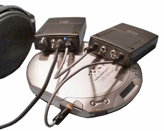
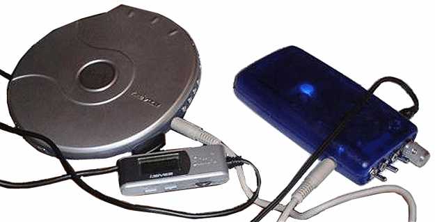
The filter works best as the input to a headphone amplifier and pairs well with my pocket headphone amplifier in the matching enclosure (shown above) for a very nice portable listening system. Both units are lightweight and will fit into many portable stereo carrying cases. The unused battery compartment in the acoustic simulator is good for storage of small accessories such as a headphone plug adapter. Finally, the price for the modified Linkwitz circuit is hard to beat, especially if one already has a headphone amplifier. The upgraded parts, case, switches and jacks came to about $20. A headphone amplifier with the modified Linkwitz circuit could be built for less than $40. If you build the Linkwitz filter with or without my modifications or have other mods you’d like to share, please don’t hesitate to e-mail me.
Thanks to Tyll Hertsens for his helpful comments.
c. 1998, 1999, 2000, 2001 Chu Moy.
Addendum
8/15/98: For better in-front localization with the Linkwitz filter, try wearing the headphones slightly forward and lower on the ears (supra-aural phones are the easiest to position this way). Experiment with the positioning to obtain the best localization. The goal is to get the sound to enter the ears at an angle, which is closer to the way normal hearing works. With the right recordings, this technique can produce a stunning sense of depth. It also works without crossfeed, but does not sound as natural.
10/6/98: Updated comparison of HeadRoom circuit to Linkwitz circuit. I also want to report that depending on the recording, the R1a setting of the perspective switch (“further from the soundstage”) can render a more 3D sound image, although the apparent width of the presentation would be fine without the additional crossfeed.
10/25/98: Added discussion about placing filter in front of headphone amp to eliminate any impedance interaction between the filter and headphones. Also clarified a few points throughout article.
11/16/98: Added image and description of portable headphone system. Also received report from user that the filter can drive Grado headphones directly with good results.
6/22/99: Added graph of time delays for the modified Linkwitz filter.
8/20/99: Mika V鳵r鄚iemi built the acoustic simulator and pocket amp in a single aluminum enclosure. He experimented with various values of C1 and R1 and found that C1 = 1uF and R1a = 50 ohms, R1b = 100 ohms had the widest soundstage and least effect on the high frequencies (Mika used the original R3 = 1000 ohms). “[B]efore I was positioned in the middle of band playing music. Now I’m in the front row as close as you can be…. Music just sounds realistic and that’s what I was looking for.” A more complete description of his work can be found in the DIY Workshop Forum.
8/26/99: Here is the parts layout and wiring diagram for Mika V鳵r鄚iemi’s simulator/amplifier project. Pictures of the finished amplifier can be see in A Pocket Headphone Amplifier.

11/23/99: Added more guidelines for customizing the simulator. Also, Chester Simpson has created a version of the modified Linkwitz with scaled parts values for headphone amps with high input impedances (greater than 250K ohms). See his article A Soundfield Simulator for Stereo Headphones.
12/9/99: Siegfried Linkwitz (himself!) e-mailed me the equation for calculating the crossfeed threshold frequency, which I have added to the article. Check out his new website: Linkwitz Lab.
1/12/00: scrazy@gcn.net.tw built this version of the pocket amp, which has a 10K ohm volume control and an acoustic simulator front-end that is based on the circuit by Chester Simpson (see design by Fred Peng below). Full details can be found at DIY Zone (in chinese only). His system consists of a Rega Planet CD Player and Audio Technica ATH-f15 headphones.


1/13/00: Fred Peng based his headphone amplifier on the acoustic simulator by Chester Simpson (which is based on the Linkwitz design), except that he replaced the R4,R6 combination in Simpson’s circuit with a 100K ohm resistor and added a unity gain input buffer stage made from an OPA134 and a high current output stage made from a PMI BUF-03 buffer. When compared with a McCormack Micro Headphone Drive, the BUF-03 driving his Grado HP-1 headphones with the simulator bypassed sounded better in the high and low frequencies than the McCormack, but the McCormack was better in the mid frequencies. With the simulator switched in, the sound was more relaxed, the low frequencies more centered, and the soundfield moved from inside his head to outside. He is very satisfied with the result and is planning to make another simulator for his Stax Lambda headphones. Full details and schematics (in chinese only) can be found at DIY Zone.


1/28/00: Added figure 1a. Thanks to Siegfried Linkwitz for sending me the graph!
5/1/00: Gus Wanner has sent in a Microsoft Excel Spreadsheet application that analyzes changes to component values of the modified Linkwitz circuit (see the text above for instructions to download). He writes:
I enjoyed your article on your modification to the Linkwitz crossfeed network. Since I have a low power (20 watt/channel) high quality amplifier integral to my McIntosh C-40 audio control center, I wanted to develop a version of this network to work with the C-40 and my Sennheiser HD-25 phones (and other headphones with greater than 60 ohm impedance). The HD25s have a maximum input level of 200mW. With the HD25s at 70 ohms, this will require a voltage of approximately 3.7 volts across each channel or approximately 11.8 volts into the crossfeed network. This voltage level corresponds to an amplifier output of 17.5 watts into 8 ohms.
To aid in doing the design, I developed a complete analysis of the Linkwitz network using the complex number analysis capability built into the MS Excel spreadsheet (and I think also available in newer versions of Quattro Pro). The spreadsheet allows you to enter values for the various components, and immediately computes the resulting levels, channel separation, and delay times for frequencies from 20 – 20,000 Hertz. Graphical plots for these parameters versus frequency are included as well.
The component values on the spreadsheet are the final values for a crossfeed circuit I designed for use with my McIntosh C-40 and my Sennheiser HD-25 headphones. The circuit is relatively insensitive to load impedances 70 ohms or greater, so it would work with other headphones as well. The modified Linkwitz crossfeed filter works great with my Sennheiser HD25s.
3/14/01: Major rewrite of article. Added detailed comparison of sound quality of filter placed before and after the headphone amplifier and review of Stax SRS-3030 headphones with filter. Added new high resolution pictures.
3/14/01: Coffin Lin put his version of the pocket headphone amplifier (with a Linkwitz crossfeed front-end) in an old TV remote control case. He modified the filter by making R2 and R3 adjustable, instead of R1. The component values in his version of the filter are:
R1: 30K ohms
R2a, R2b: 15K, 10K
R3a, R3b: 50K, 100K
R5: 33K
C1: 3,300pF
R4: 33K
C2: 10,000pF


The resistors are Dale RN55D. About making R2 and R3 adjustable, he says:
I mistook R2 for R1, but on the Excel worksheet simulator, R2 can still alter some balance. I think that adjusting R3 is more effective than adjusting R2 (I forget which switch is for what resistor.) One has more stereo (good for dance and rock) and the other is more natural (good for jazz).
3/25/01: Changed the value of R3 in figure 3 to 910 ohms (originally 1K-ohms) to remove emphasis in lower midrange and to increase the treble boost. This update results in a more balanced, clearer sound. I STRONGLY recommend it.
3/27/01: R2 and R3 incorrectly drawn in figure 3 from 3/25 update. Fixed.
11/24/2001: Mark D. Johnson writes:
I just finished building your Acoustic Simulator and have been auditioning it over the last several days on my Sennheiser HD600s (even now I’m listening to Miles Davis as I type this). I just want to tell you how much more I’m enjoying my music and how much less fatiguing it is to listen for long periods of time.
The thing I like best of all is the three dimensionality I hear in recordings that was never present before. As a drummer, the most amazing thing to me is that I can actually hear (whether true or not) the location of individual drums/cymbals being played – and not just sound coming from a point source called “drums.” On the latest Dianna Krall CD I could hear even elevation changes taking place as different cymbals were struck. Again, whether or not this is just a byproduct of the design I cannot be sure, but it sure makes listening more enjoyable.
5/21/2002: J. Ian Ramsey (from the forums) built a pocket amp and the high impedance version of the Linkwitz acoustic simulator in separate enclosures. He obtained most of the parts from RS Components Ltd. For the 120nF cap (C2), he paralleled two caps: 100nF and 22nF. He writes:
I made the Simulator in the high impedance version as recommended by Chu in the project notes. I have increased the gain of the amp from x11 to x17 by putting a 1.5K resistor in parallel with R3 (1K) to compensate for the insertion loss of the simulator which is only used between the source and the amp.
I laid out the simple circuit for the acoustic simulator in stripboard. The simulator effect is very subtle and at first I was unsure if I had made mistakes in the layout, which were preventing the correct circuit action. Listening to this year’s Grammophone magazine Award winner – Vaughan Williams ‘A London Symphony’ confirms the following:
- With the simulator switched to B the whole soundfield is very gently more centre focused and there is a slight loss of ambience.
- Switched to A, the field narrows and the volume level drops slightly thus making the sound image appear to be heard from a greater distance – just as Chu remarked in the article.

Overall I could easily live without the simulator as my HD600 headphones with the cmoy amp are very, very good. As an intellectual exercise, the concept of the simulator is satisfying in the way it addresses some of the headphone effects against speakers and this design does not degrade the sound – so I will most likely continue to use it.
Chu was spot on when he said to spend time with it in the design values as one would soon tire if the values were changed to produce a more dramatic effect. The subtlty soon gives way to a distinct change with it in and out and between mode A and B. Congratulations and thanks to Chu Moy for these brilliant designs.
5/21/2002: Phidaeaux (from the forums) built a pocket amp and the high impedance version of the Linkwitz acoustic simulator in a single enclosure. The white LED power indicator is mounted on the circuit board INSIDE the transparent Serpac enclosure. He writes:

Ok, I just finished this bad boy, and man oh man, am I pleased! This thing sounds so good. I’m only driving 32-ohm phones (Sennheiser HD497s) but the difference in sound quality is VERY obvious over my SlimX MP3/CD player’s built-in amp. It feels good to have power to spare, instead of driving the stock amp to its limits. Also, the crossfeed is very nice. I didn’t really notice at first, but now that I can sit down and play with it, I really like how it sounds. 
First off, thanks much to PRR, cmoy, tekir, tangent, and everyone who had either helpful suggestions, or had problems in the past, that I could read about and avoid doing myself. Cmoy and tangent’s info were both very useful too, for both the obvious reason (the schematics) but also the piles of helpful tweaks and pictures they had.
Technical notes! I’m using all the ‘usual suspect’ parts: Panasonic pot, Digikey jacks, metal film resistors, polypro caps (except for the power supply caps, which are electrolytic). I’m using a Burr-Brown OPA2134 dual op-amp (in a nice machined socket).
The crossfeed circuit is a pre-amplifier modified Linkwitz (the same circuit that cmoy uses as an independent item) and has had its resistor values all multiplied by 10, and its capacitor values divided by 10. This was done to raise input impedence a bunch, because its not actually driving headphones, it just connects directly to the amplification stage. The two ‘perspective’ settings are 2000 ohms, and 1500 ohms.
I thought about replacing one of those with a pair of mini pcb-mount multiturn pots, so I would have a ‘default’ setting and then a ‘custom’ setting I could adjust by opening the case. Or maybe put a ‘stereo’ pot controling those values, and cram it somewhere else on this case. Who knows. Anyway, I’m satisfied with those two values for now, I’ll wait before I do any ‘tinkering’. 

Anyway, to those who said it could not be done, I managed to fit the following panel items in the case: input and output jacks, one on each side of the case. I’ll get some right angle adapters I think to clean it up a bit, so it doesn’t have the plugs sticking off to the side like cowlicks. Power switch, crossfeed bypass switch, crossfeed perspective switch and Panasonic EVJ volume control (with pretty aluminum knob) are all on the front panel. The volume control, and the crossfeed switches are touching each other. They are quite literally pressed up against each other inside that panel!
White LED. Looks good shining out from inside the case. Bright too. I was going to use a blue, but the blues were less efficient than this white (oddly enough). I’m running it with a 2.2k resistor. Current through it seems to be about 3mA. That could stand to be lower, and the LED is very bright right now. If I make another modification, it’ll be to dim that LED a bit, and save some power. You can see neat little shadows inside the case from the components, light glinting off of things inside there. Very cool.
I also really like this Serpac H-65 transparent blue case. I’m all about form AND function. I know that people usually get on one side of the fence or the other. They either LOVE pretty little gadgets, regardless of how they actually work. And then there are people who say “Screw it, does it work right? Then it can be ugly, I don’t care.”
For me, I want it to look good, work well, and feel ‘right’. If I’m going to be using something every day, it needs to be ergonomically designed. Engineers are notorious for totally forgetting the fact that real people have to USE the things they build. I work with equipment that was NOT inuitively designed so often; its like a breath of fresh air to find equipment where someone actually sat down to use it for a while, and thought ‘huh, this knob should really go down here on this side, instead of up here… that would make a lot more sense.’
It’s so easy to figure out where controls should go. Everything flows left to right on mine. Left is the input, right is the output. Starting from the left on the panel, you can turn it on or off, then you can choose crossfeed on or off, then you can raise or lower the crossfeed, then you can change the final volume. I don’t need labels, cause it makes sense. And then, I love this case. Its curvy and sexy, but still has quite a bit of internal volume. The transparent blue doesn’t scream “I bought this at Radio Shack like a nerd!” but rather, “This is a modern piece of technological wizardry.” But at the same time, you can peer inside and see the parts, making a muted statement that it was a DIY project. The LED inside is nice too. Don’t have to use up a panel spot, and the inside of the device lights up all pretty. Form AND function. Together at last!
Anyway, I don’t mean to lecture you guys; you all build very good things. I got the ideas for this from seeing various other projects people have built. I just urge you all to take note of the stuff you deal with every day, and while you are thinking about all the technological aspects of it, to give a thought to intuitive design and control placement, the delicate art of making something ‘easy to use’ regardless of what its actually doing, etc.
Also, read the book “The Design of Everyday Things” by Don Norman. It talks about doors, VCRs, ovens, and all sorts of things you use every day, but don’t think much about. Ever push on a door when you are supposed to pull? Everyone has! But why? It’s a simple matter to make the operation of a door obvious; you don’t even need ‘push’ and ‘pull’ signs that people have to look at and read. A well designed door gets used right each time, without anyone even noticing. It’s all about intuitive engineering and human-centered design.
Oh, more technical jibba-jabba. Gain on the amp is set to 11. Current measured while in use, at a moderate volume, is 12mA. Not too shabby. Voltage between ground and the rails is 4.40V and -4.41V while in operation. Not bad, if I do say so myself! This single 9V is plenty to drive the 32-ohm HD497 to utterly insane levels. No need to give it more voltage.

[…] more information about acoustic simulators, see A Quick Guide To Headphone Accessories, An Acoustic Simulator For Headphone Amplifiers and Technologies for Surround Sound Presentation in […]
LikeLike
[…] found a good article at HeadWize by Chu Moy. Basically I had two problems – the filter had a high output impedance and the channel […]
LikeLiked by 1 person